Full Adder and Half Adder circuits and Truth Table | complete explanation
 |
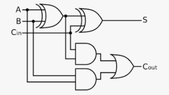
| Full Adder Circuit |
 |
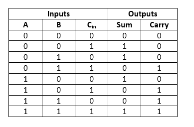
| Full Adder truth table |
 |
| Half Adder Circuit |
 |
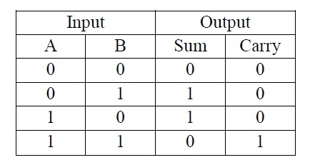
| Half Adder truth table |
In combinational circuits, different logic gates are used to design the encoder, the multiplexer, the decoder, and the multiplexer. These circuits have some characteristics as the output of this circuit depends mainly on the levels present at the input terminals at any given time.
This circuit does not include any memory. The pre-input state has no effect on the current state of this circuit. The inputs and outputs of the harmonic circuit are "n" no. of the input and "m" no. of the outputs. Some harmonic circuits are half collector and full collector, subtractor, encoder, decoder, multiplier and demultiplexer. This article covers an overview of half of the adder and the full advertisement as it works with truth tables.
What is Adder?
Adder is a digital logic circuit in electronics that is widely used for adding numbers. In many computers and other types of central processing unit, processors, extensions are used to calculate addresses and related activities, calculate table pointers in the ALU (Arithmetic Logic Unit), and even use them in other parts of the processors. It can be constructed for many numerical representations such as increment 3 or decimal encoder binary. Adders is mainly classified into two types: half Adder and full Adder .
What are the adder half and full circle?
The half adder circuit has two inputs: A and B, which add two numbers to the input and create a load and sum. A complete adder circuit has three inputs: A and C, which add three input digits and generate a load and sum. This topic offers detailed data about the goal of the full adder and the half adder in tabular forms and even circuit diagrams as well. It has already been mentioned that the main and primary purpose of plugins is to add. Below is the detailed half-snake and full-snake theory.
half Adder theory
So, when accessing the half-Adder scenario, it adds two binary numbers where the input bits are labeled as addition and addition and the result will be two outputs one being the sum and one carrying. To perform the sum operation, an X-OR is applied to both inputs, and an AND gate is applied to both inputs to produce the load.
Whereas in a full adder circuit you add 3 digits of one bit, where two of the three bits can be referred to as operands and the other is called carry bits. The output output is 2 bits output and can be referenced as the bearing output and sum.
With th half adder, you may design a very simple addition with the help of logic gates.
Example :
PCBWay
The 2-bit Half-Adder truth table is as follows:
Half-Adder truth table
0 + 0 = 0
0 + 1 = 1
1 + 0 = 1
1 + 1 = 10
These are the lowest possible single-bit combinations. But the result of 1 + 1 is 10, the result of the sum should be rewritten as a 2-bit output.
Thus, the equations can be written as:
0 + 0 = 00
0 + 1 = 01
1 + 0 = 01
1 + 1 = 10
The output '1' of 10 is executed. 'SUM' is the normal output and 'CARRY' is the execution.
It has now been shown that 1-bit declaration can be easily implemented with the help of the output XOR gate of 'SUM' and the AND gate of 'Carry'.
For instance, when we need to add 2 (two) eight-bit bytes together, it can be implemented using a full-feed logic circuit. Half Adder is useful when you want to add quantities from a binary number.
One way to develop binary number speculations is to create and reduce a truth table. When you want to make a three-digit collector, add the half adder is done twice. In a similar way, when you decide to make a four-digit snake, the operation is performed again. With this theory, it was clear that the implementation is simple, but the development is a time-consuming process.
The simplest expression uses the exclusive OR function:
Sum = A XOR B
load = a and b
And the equivalent expression in terms of the fundamentals AND, OR, and NOT is:
SUM = A.B + A.B'
VHDL code for Half Adder
port (A: in STD_LOGIC;
b: in STD_LOGIC;
sha: out of STD_LOGIC;
cha: out of STD_LOGIC);
Started
sha <= a x or b;
cha <= a and b;
end of behavior
half number IC
Half Adder can be implemented by high speed CMOS digital logic circuits such as the 74HCxx series which includes the SN74HC08 (7408) and SN74HC86 (7486).
Half Adder Boundary
The main reason to call these binary adders as Half Adders is that there is no scope for including the overhead bit using a previous bit. So, this is a very important limitation of half adder that were once used like a binary adder especially in real time situations that needs adding multiple bits. So this limitation may be overcome by using full plugins.
full Adder
This adder is difficult to implement when compared to the half snake.
The difference between a full adder and a half adder is that a full adder has three inputs and two outputs, while a half adder has only two inputs and two outputs.
The first two inputs are A and B and the third input are inputs marked as C-IN. When the ultimate adder logic is designed, you string 8 of them together to make and create a byte level collector and carry bit sequences from one feed to another.
The output load is set as C-OUT and the normal output is represented as S which is "SUM".
By XORing the inputs provided "a" and "b"
Then the result of A XOR B is XORed with C-IN
This only generates true SUM and C-OUT when any two of the three inputs are HIGH, then C-OUT will be HIGH. Therefore, we can implement the complete adder circuit with the help of two half circuits. First of all, half adder will be used to add X and Y to produce a partial sum and 2nd half adder logic may be used to add C-IN to the sum produced by the first half adder to get S (final result).
If any of the half adder's logic produces an overhead, there will be an output overhead. So, C-OUT will be a function or output of the curry half-snake. Take a look at the full snake circuit implementation shown below.
Larger logical diagrams can be implemented using the complete adder logic above, where mostly simpler symbol is used to represent the operation.
With this type of symbol, we can add two bits together, taking a load from the next lowest order of magnitude, and sending a load to the next higher order of magnitude. In a computer, for a multi-bit operation, each bit must be represented by a complete binder and must be added simultaneously. Thus, to add two 8-bit numbers, you will need the full 8 additions that can be formed by the sequence of two 4-bit blocks.
Half adder and full adder using K-Map
The sum and outputs of the half-snake load can also be obtained using the Karnaugh map (K-map) method. The half adder and the full adder logical expression can be obtained through K-map. Therefore, the K-map of these additions is discussed below.
Half Adder K-map is:
HA K-Map
HA K-Map
Snake full K-Map is
FA K-Map
FA K-Map
Boolean expression for SUM and Carry
= A’B’Cin’ + A’B’Cin’ + A’B’Cin’ + AB Cin’
= Cin (A’B’ + AB) + Cin’ (A’B + A B’)
= Cin EX-OR (A EX-OR B)
= (1,2,4,7)
= A’B Cin + AB’Cin + AB Cin’ + ABCin
= AB + BCin + ACin
= (3, 5, 6, 7)
A harmonic circuit combines different gates in a circuit where it can be an encoder, decoder, multiplier, and demultiplexer. The characteristics of harmonic circuits are as follows.
The output at any point in time depends only on the levels at the input terminals.
It does not use any memory. The last input state has no effect on the current of the circuit.
It may have any number N of inputs and m number of outputs.
VHDL encoding
The VHDL encoding for the full tool includes the following.
The full_add entity is
port (A: in STD_LOGIC;
b: in STD_LOGIC;
cinema: in STD_LOGIC;
sum: out of STD_LOGIC;
cout: out of STD_LOGIC);
end full_add ;
The behavior of the full_add architecture is
The hectare component is
port (A: in STD_LOGIC;
b: in STD_LOGIC;
sha: out of STD_LOGIC;
cha: out of STD_LOGIC);
Final Ingredient
signal s_s, c1, c2: STD_LOGIC;
Started
HA1: ha port map (a, b, s_s, c1);
cout <= c1 or c2;
end of behavior
The difference between the half adder and the whole adder is that the half adder produces the results and the full adder uses the half adder to produce some other results. Similarly, while the Full-Adder is two Adder halves, the Full-Adder is the actual block we use to create the arithmetic circuits.
Related topics:
xor truth table
full adder circuit
nand gate truth table
jk flip flop truth table
nor gate truth table
full adder truth table
xnor truth table
xor table

0 Comments
Post a Comment